Hi there, welcome to the Meganton Tech Channel Blog. This blog accompanies my YouTube channel, with more detailed and background information on the topic in my video’s and other topics that don’t lend themselves to put into a video. These topics will range from showing off old electronics, new gadgets, DIY topics on computers and electronics, such as tinkering with Raspberry Pies, but also radio-controlled stuff like quadrocopters/drones and even some photography and video stuff. So everything I like to do, that has to do with tinkering and tweaking electronics. I hope you like it too!
Disclaimer: I am NOT a electronics or computer professional just a self-taught hobbyist, so all topics but especially the DIY topics documented here are only to show you how did things. These may not be best practises and if you used them, you do them without guarantee on your own risk.
The Gotek USB floppy emulator, especially with the open firmware Flashfloppy has become a staple for many retro enthusiasts for upgrading old computer systems with a “modern” solution for loading software on the old systems. I am also one of these enthusiasts. As a retro system builder especially of the IBM-PC compatible kind, I am used to configuring these systems using jumpers. No “plug and play” feature here. The Gotek has also some jumpers you must set for using it on an IBM-PC. IBM-PCs make use of a cable that you can connect to two disk drives to one controller.
The selection of which drive is drive A: or drive B: is determined by the distinctive twist in the cable between the connector in the middle and the connector on one of the ends. If the drives you want to connect have jumper for setting the drive ID then both drives need to be set drive ID 0. This is especially the case for most 5 1/4 inch floppy drives, the later 3.5 inch disk drives often do not have drive ID jumpers and are set to ID0 by default.
The Gotek floppy emulator has also such a jumper S0 en S1 and this needs to be set to S0. However, there is another jumper JC on the Gotek, which in conjunction with the setting in the FF.cfg file (see highlighted code below the image) for flash-floppy to determine that the drive is in IBM-PC compatibility mode. I configured several Goteks in this way on my retro IBM-PC systems.
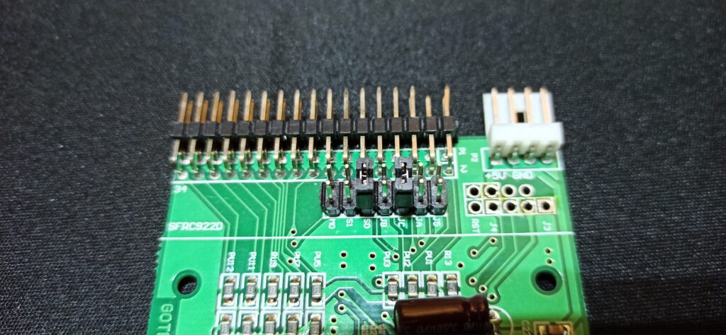
The default Gotek jumper setting for IBM-PC, bridging S0 and JC
So having this presumed knowledge I got a new Gotek drive in and set the S0 en JC jumper and connected. But to my surprise, the drive did not work. Troubleshooting went from, checking the FF.cfg on the USB drive used, trying different locations on the cable, using a known working cable, checking with a known working Gotek and floppy drives, also in combination with the new Gotek at different positions on the cable, even reflashing the firmware and checking the disk controller. All to no avail. I even started thinking I was duped out of my money by a fake unit. So I started examining the board of the Gotek. I knew there were different incarnations of the thing, some versions best to be avoided. Then I noticed that the New Gotek was different from the previous working one.
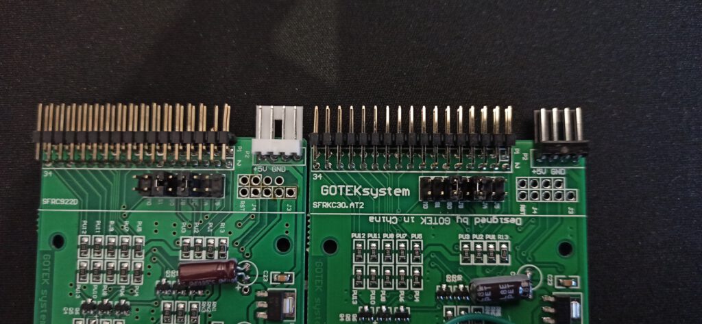
Two different version of the Gotek, left my older SFRC9220 and to the right my newer SFRKC30.AT2 version. Note that label JC is missing from the third jumper from the right.
Gotek SFRKC30.AT2 has no JC jumper!!
The older Gotek I had laying around had as board number SFRC9220, the newer Gotek was labelled “GOTEKsystem” with board number SFRKC30.AT2. I was already reading through the Flashfloppy wiki to see what could cause the problem and was now looking for information on this particular iteration of the Gotek. In the Gotek compatibility section, some are listed and there I noticed this side note: “SFRKC30.AT2 (QFN32): Missing the original rotary-encoder header, but features the new KC30 rotary header. Also missing JC jumper location.”. A bit confused I looked back at the board and now noticed the JC label was missing from one of the 7 jumpers, but there was a jumper header. This jumper header is not functional, so even when bridged a Gotek SFRKC30.AT2 with USB stick having the interface=jc setting activated in the FF.cfg file, will think the drive is in shurgart mode not ibmpc mode. And voila, changing this setting in the FF.cfg file from settings=jc to settings=ibmpc made my new Gotek work flawlessly on my 286 build.
So to summarize, when using a Gotek with board SFRKC30.AT2 in an IBM PC compatible, you only have to set jumper S0 and make sure that the flashfloppy FF.cfg file has the interface parameter set to ibmpc and not jc.
A part of my retro-computer collection consists of several Commodore-64s. The C64 was the computer that I wanted as a 12-year-old but did not get… I am only discovering it now. One of the machines I have was a great secondhand deal.
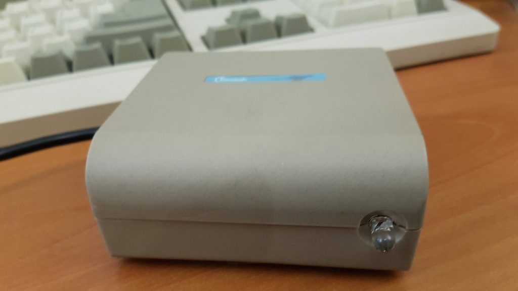
It’s a C64 complete with a datasette player, floppy drive everything had still its original box. I also came with an extra box, with random computer stuff. Besides a collection of cassette tapes with software and a collection of EPROMs, the previous own programmed custom kernals, this box also held a strange peripheral that I had not seen before. A beige box with a black cable having an 9 pin joystick connect attached and one clear led, or at closer inspection an IR receiver. The box had only a label on the top reading “Cheetah”. On the bottom were 3 rubber feet, but no label with a model number of sorts. At first instance, I even doubted if this was a genuine sold product or someone’s DIY project.
The beige box in Question
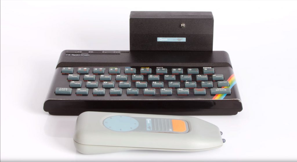
Because I thought it was a wireless, IR-controlled peripheral, I started Googling with catchwords such as “infrared” “joystick” “c64” “cheetah” with images, but I didn’t see the box that I had before me. But via the name Cheetah, actually Cheetah Marketing, a British manufacturer of peripheral devices, mostly joysticks for the 8-bit computer generation and also sound and music-related peripherals, I came across the Remote Action Transmitter (R.A.T.). The different articles only referred to the version for the ZX spectrum and mostly to dated photos of what that thing had looked like. But in the end, I also found an episode (#34) of Paul Jenkison’s “Spectrum Show” on Youtube where this device is revealed. It consists of an IR receiver in the form of a plug-in module for the ZX spectrum (which did not have a joystick port) and instead of a joystick, a remote control with a joypad and fire button designed as membrane buttons. So I went digging in the box to see if I could find a remote control and yes it was.
The controller as shown in episode 34 of Paul Jenkinson’s Youtube channel “The Spectrum Show”
This remote control is identical to the one shown in the “Spectrum Show” episode. The remote control gets its energy from a 9V block battery and has two IR transmitters on the front. For operation, you need two hands because you operate the fire button with one thumb and use the other thumb for the joypad. The joypad is of course not analogous like a “real” joystick. There are eight specific positions that the joypad recognizes and transmits to the receiver. In my case, it is the receiver that makes it special, because it can probably be used on all machines with an 8 pin joystick port (Commodore, Atari), instead of the specific ZX spectrum plug-in module. Anyway, would I really like to use this thing? The idea of having a wireless game controller in 1984, it is way ahead of its time. Wireless controllers have only become commonplace with the fifth generation of consoles in 2005-2006. The implementation of the idea in 1984 is not good and actually more of a gimmick. The fact that you have to use the thing with both hands and aim properly and still are “treated” with poor response times, makes it more aggravating than something useful. The device can indeed be used from quite a distance but it also means squinting to see the little CRT of that era. No, in my view the R.A.T. more a nuisance, then a blessing. Probably, therefore there are very few left, and that makes it a rare item.
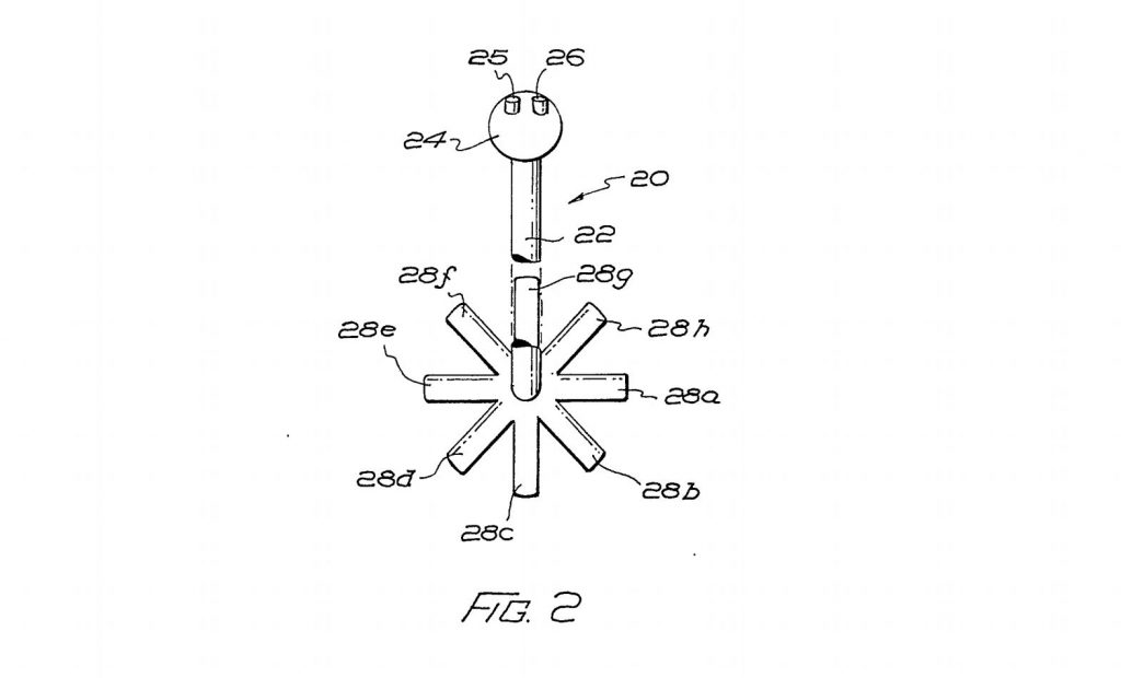
A drawing of the initial design of the R.A.T., rather as a joystick, in Cheetah patent application GB2158667
On one of the advertisements for the R.A.T., I saw “Patent Pending”. This aroused my interest because I know my way around the various patent databases. Could I trace the patent on that device? Yes, the British patent no.2158667 filed by Cheetah Markting on May 3, 1984 and granted on January 20, 1988, describes the wireless game controller. However, the configuration in the drawings differs from the device that appeared on the market. The controller started more as a joystick than a joypad. A joystick with two fire buttons on the handle which would make moving and firing with one hand possible. However, I see that this design would have led to problems. As said earlier, the infrared transmitter can only encode eight specific positions and send them to the receiver. To overcome this for a joystick, which can in principle take up an infinite number of sub-positions, the thought of something. The patent shows a joystick, that cannot move around freely, but an opening in the form of an eight-pointed star in the foot guides the user of the joystick to one of the 8 positions when moving the stick from the centre, from one position to the other is therefore only possible by returning to go through the centre. This looks like an innocent idea, but every joystick user knows what the scenario will be if you start to play. In the “heat of the moment” you will use force and break the stick or the foot. I wonder if Cheetahs engineers realized this, redesigned it as a joypad or that real joystick prototypes were made that broke after a short torture during testing. One can only wonder.
Yikes, it took some time, before I had time to pick up on my Blog and Vlog again. But after a break of almost 2 years, we’re almost there! I will shift my topic more towards the Retro-Tech side instead of the Multi-room speaker (Volumio/Max2Play) centred subjects, that I made earlier.
In the meanwhile, I build quite the collection of Retro (computer) stuff. I also now have a nicely equipped electronics lab to be able to do some serious soldering. I have also so some ideas for mini tech documentaries with a focus on the history of computer in the Low countries. For this restart, I have also a new intro that you can watch as a teaser of what’s coming.
When I started my Youtube channel last year around this time, I was in between jobs and had quite some time on my hands to release some video’s. Inspired by the likes of Techmoan, 8-bit guy and others I started to post some video’s on tech stuff I was working on at the time. It took some courage to get in front of the camera and put it out there. But I was quite pleased with result especially when I found that a lucky item on the combination of Volumio and Spotify Connect clearly struck a cord.
It was merely spreading the word of a solution which was discussed in a niche forum, to the wider public of people using Youtube as an information resource. A nice amount of views and hartwarming comments were the result, Thanx for that everybody. This is of course something I liked to continue, but then there was this new job, Damn!
No, that really is a positive thing of course. But time became more scarces especially due to my 3 hour commute every working day, resulting just one posted video in September. But my channel has been on my mind, writing down topics, reading up and getting my hands on voice assistants and AI on the Raspberry pi, FPV quadrocopter things, vintage electronics like some nice Sony walkmans and Commodore Amigas. In the meanwhile I found a home closer to my new job and will be moving there beginning next year. At my new house I will have space that I can dedicate as an electronics “lab” and studio, so I am planning a “relaunch” in the spring next year. So thanks for your support so far and bear with me. As T-800 Arnie would say: I’ll be back!
In a previous post, I discussed a plugin for Volumio to add Spotify connect ability to this headless audio-player OS. I also pointed out that the competing OS, Max2play did not seem interested in incorporating this feature in their OS. A missed chance in my view, as there was a clear appetite for it if you checked the feature requests on their forum.
But they clearly took up the gauntlet, and after perfecting their plugin infrastructure and suggesting to the user community they could create a Spotify connect plugin, they came with such a plugin themselves. It is still a beta version, with still some stability issues but if it is running, it works as it should. This plugin has some prerequisites: It will only work if you’re a Max2play premium user (€9,99/year) and a Spotify premium user. In this sense, Volumio with the Balbuze plugin is still the cheapest solution.
Installation is quite straightforward, but also a bit more hassle than Volumio, especially when you are also using also other audio-players such as Squeezelite on Max2play. You can find my video tutorial and demonstration of the functionality below. As already said there are some stability issues. After some time the device Max2play with the Spotify connect plugin installed and running disappears from the list of available devices in the Spotify App. Stopping and restarting the instance of the plug-in will deal with this, but this should not be needed.
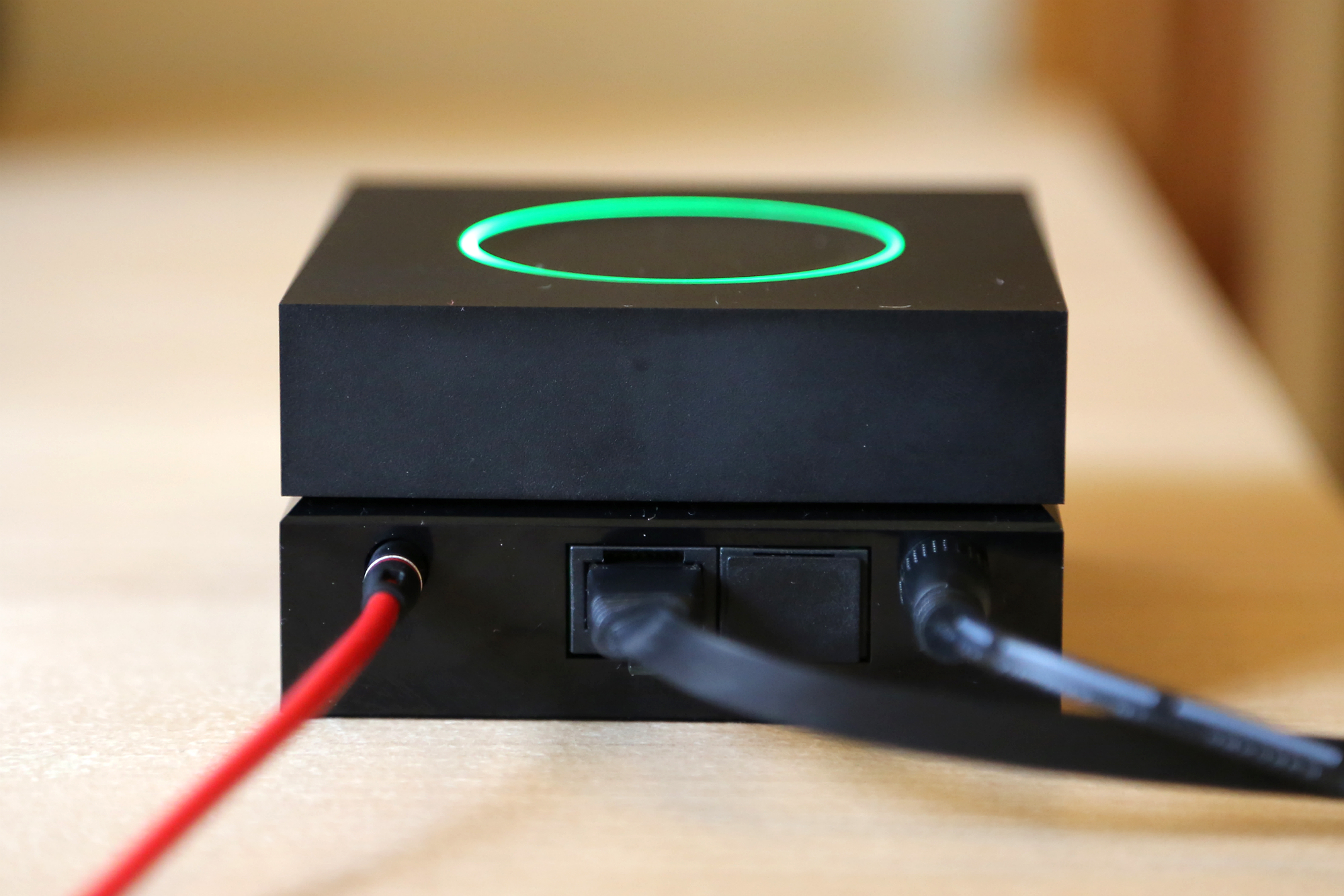
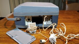
So far my blog and video’s has been about DIY tech stuff with a focus on audio. This time we stay in the realm of audio but go back time. Way back even before even I was born, because I would like to show you an old audio device that I saved from the skip somewhere in the 1990’s but was produced in the late fifties early sixties. It even still works (sort of). It’s an old table-top reel to reel tape recorder made by the technology pride of the Netherlands: Philips, more specifically the EL3515A model. This EL series of reel to reel tape recorders have been produced by Philips from 1957 onwards to 1968. But this EL3515A is an early model. The “A” indicates that it is a more luxurious version of the basic EL3515, with a wooden case covered with fake leather instead of a plastic case. It is pre-transistor device and its electronics is still based on radio tubes. One of the tubes is used for the “magic eye” which is in the big stop button, which lights up green when the device is on and should show the recording level. This is one of the first models with such a “magic eye”. The whole package comes in the form of a carrying case that is 370 mm wide, 160mm high and 320 mm deep.
The power cable and a separate mono microphone can be tucked away in a small compartment on the right side of the case with a removable lid. The whole thing has a hefty weight of around 8 kg, mainly because all the electronics and moving part are mounted in a cast-iron frame that resides in the wooden case. Because of this, I would not call it a mobile device. It runs off AC power switchable between 110, 127, 220 and 245 Volts. It is a mono device with around 2-2.5 Watts output. When you remove the plastic cover, you can see that it uses 9 to 13 inch tape reels. It plays and records two mono tracks (two sides) running at a speed of 9.5 cm/s.
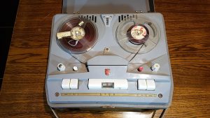
After plugging in the power socket, you can switch it on by turning the left volume button. The whole thing directly springs to life with the hum of the drive motors, but playback can only be heard after a short warm-up until the “magic eye” is at its full intensity. It is very basic machine, the extreme left and right buttons are for winding back and forth, then you have on the left, a pause button, on the right the play button and the big button in the middle with the “magic eye” is the stop button. Between the two reels there is also a counter present, but this is broken on this machine. The turning nobs on the extreme left and right are on/off and volume left and the recording level on the right. The smaller nobs next to them are tone adjustment on the left and the red recording button on the right.
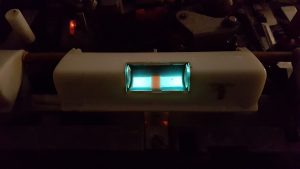
The “magic eye” lighting up in the stop button
When I rescued it from the skip somewhere in the 1990’s, it still worked fine and I used it as a novelty when my little nieces and nephews were visiting to record their voices and playing them back to them. That was always a lot of fun. Now it seems that the amplifier part of the device has deteriorated, playback and recording levels are low. It first off all would need a thoughrough cleaning. As it is now standing in storage, I am thinking to sell it off. Its seems that there are still some enthusiast out there who collect these things or scavenge them for the radio tubes. These tubes seem then to find their way into all kinds of DIY projects. When researching this device for this blog and my youtube video. I also came across an advertisement from the Leidsche courant from 1959 with prices for the EL3515, EL3515A and the more advanced EL3538. The EL3515A was priced at 398 Dutch guilders in 1959, which translates in a value of € 1 219.42 in todays money (Calculated with the tool here.), but I think I will make my asking price as a serious lot lower! If you want to see the EL3515A in action please watch my youtube video below.
In previous posts I already talked about all these different headless audioplayer operating systems there are for small single board computers such as the Raspberry Pies (eg. Volumio and Max2Play). I also discussed that I am a Spotify user and love the Spotify Connect feature and the multiroom speaker possibility it brings. But the two audioplayer OSes that I am current testing did not support Spotify Connect so far, so I am currently resorting to a multiroom setup using Max2Play, Logitech Media Server (LMS) and the “triode” Spotify plugin to control several devices (RPis with Squeezeplayer software/Squeezebox duet receiver) for audio playback. It works, but the look and feel of LMS is very dated, so I am still on the lookout for improvement and I am not alone. The requested features section of the user forums of both Volumio and Max2Play show major interest in Spotify Connect. However the developer(s) of Max2Play does not seem to warm-up to this feature, while it trumps to be the multiroom audio centered OS. A missed chance in my view. In the meanwhile, Volumio has beaten Max2Play to the punch via support of third party plugins and the coding work available at Github of user “Balbuze” which seem to be based on previous work of “Fornoth” and “Plietar”. I am planning to test Balbuze’s Spotify Connect plugin “Volspotconnect” in Volumio shortly on my Pi Zero that currently runs Max2play. The plugin is specific for ARM6 and ARM7 chip based computers such the Rasberry Pi’s, so if you are running Volumio on a Intel machine, bad luck for now. It is a basic plugin that just makes your Volumio device show up as a Spotify Connect device. It has no connection with the Volumio interface yet, so no control via this interface or cover-art. This is no problem as you would rather use the Spotify software or app to control playback. It is clearly a work in progress. I also thought that you also needed a Spotify app developers key, which your can request here. However commenter Wim, indicated that this key is already present in the zip file provided by Balubuze. That makes it even simpler, I hope to have time soon to get this up and running. This also seems a good topic for a Youtube tutorial so stay tuned!
In an previous post, I discussed that I have been using the Logitech Squeezebox Duet and Logitech media server (LMS) software, to be able to play my mp3 collection and stream audio from Spotify. But the iPod shaped Duet controller, over 7 years old, got some issues charging its battery. I am hoping to be able to fix it, but in the meanwhile I wanted a bit of a replacement, to control audio playback, without using for example, the “Squeezer” app on my android phone.
The Logitech Squeezbox Duet controller.
Before I bought the Squeezebox duet somewhere in 2009, I had been experimenting with a touchscreen based solution in combination Asus eeebox mini PC, but wasn’t really satisfied. Then came the Squeezebox duet along and I replaced the touchscreen setup for it. However, I kept the LG Flatron L1510SF 15-inch touchscreen. Now in 2016 one of the best community supported mini PCs must be the Raspberry Pi. I have also been playing with it to make both video and audio-player devices. There is also already a whole range of supported small touchscreens, which connect via the GPIO header or Display header, but using screens with HDMI, DVI, or VGA input and USB for the touch-control seems not so common. But when my Squeezebox Duet controller got issues charging, I was thinking why not pair my old 15-inch touchscreen with a Raspberry Pi running LMS?
Setting up Logitech Media Server (LMS)
Setting up a Raspberry Pi with LMS is very simple when you use the Max2Play audioplayer OS. Just download the SD image from the Max2play website, write it to the SD card with a tool like win32diskimager. Insert the SD in the Rpi, connect the Rpi to you network using an ethernet cable and power it up. You now can enter the setup of Max2play on you Rpi, by typing the URL: max2play/ in your browser. In the setup interface you can select to install LMS and the Squeezerplayer playback software onto you Raspberry Pi automatically. In this way you have a headless audio server device, which can playback songs locally or on other squeezebox devices on your network. You can control it via an app like Squeezer on android or by logging into the LMS server web-interface on your laptop or PC.
Jivelite, the touchscreen interface for LMS
The LG Flatron L1510SF USB controlled touchscreen.
In my case, I wanted to use a local touchscreen display to control Rpi with LMS. For this, you have to do some extra work. First of all, you need to connect the screen and also for setup purposes, a keyboard and mouse. Secondly you need to install the JiveLite Squeezebox interface software via the Max2play setup. This is a Max2Play premium feature which costs you a license fee of €9,99 per year. It is possible to setup LMS and Jivelite without Max2Play, but not as effortless as provided by the setup interface of Max2play. The JiveLite setup in Max2Play lets you also select several JiveLite interface skins, but these are tailored to the smaller Raspberry Pi specific touchscreens and needed some modification to get a fitting layout for the 1024×768 resolution of my LG touchscreen. But more about that later.
Calibrating your USB touchscreen
Now we first need to get the USB touchscreen working with the Raspberry pi. When researching how to do this, I came across this article (in Dutch). Which describes the process for the exact same screen as I am using. First of all, you need to install xinput-calibrator. You best do this locally on your Rpi using the attached mouse and keyboard by opening a terminal window and typing sudo apt-get install -y xinput-calibrator. You now have to run xinput-calibrator by typing xinput-calibrator. This will open a window for calibration. You can follow the instructions for calibration and use a stylus for best precision. This will result in an output window with calibration parameters that need to be put into the /etc/X11/xorg.conf.d/99-calibration.conf file. I did this with the parameters I recorded but run into problems. The LXDE gui would not show after a reboot. So in the end, I just used the exact same settings as described in the article with the exact same LG touch screen. That did the trick, the touchscreen is working fine.
Making the Joggler skin fit your resolution
Now I wanted the have a JiveLite skin that was a good fit with the resolution of the screen. The Joggler skin, came nearest to what I wanted but needed adjustment to fill the whole screen. For this you need to edit the code of skin file: /opt/jivelite/jivelite/share/jive/applets/JogglerSkin/JogglerSkinApplet.lua
And edit line 259 so it reads: Framework:setVideoMode(1024, 768, 0, false) where 1024 and 768 reflect the resolution and aspect-ratio of the screen.
When you want the spectrum visualizer of Jivelite to show correctly (Only visible when playing audio locally on the LMS machine). You also need to edit the following section in the JogglerSkinApplet.lua file. The values to edit are shown in bold
spectrum = {

position = LAYOUT_NONE,

x = 0,

y = 2 * TITLE_HEIGHT + 4,

w = 1024,

h = 566 - (2 * TITLE_HEIGHT + 4 + 45),

border = { 0, 0, 0, 0 },

padding = { 0, 0, 0, 0 },
After a restart of the Jivelite GUI, or reboot of the system, the layout should have a good fit with the resolution of the screen. Some buttons may still not have the most perfect scaling, but it is all functional. I however will, keep an eye open for a more perfected 1024×768 skin for JiveLite. If you a reading this and have one or knows one, please let me know.
Finally
One small thing is still bothering me and this is the visible mouse cursor. Max2Plays add-on, specific for the smaller Raspberry Pi touchscreens, has a very handy checkbox to make the mouse pointer on a touchscreen invisible. But as my touchscreen is not supported by this add-on, I cannot use it. Any suggestions to make the mouse pointer disappear are also very welcome. To get a better impression of how it works and what it looks like I recommend you to watch my youtube video about it, here below.
In my previous post, I discussed the problem with the Medion P69055 WiFi multiroom speaker and Spotify connect. It could and should support Spotify connect, but most probably lacks a firmware update to enable this feature. A big let down by Medion, but how to solve this? In the end, I opted just to use the line-in of the speaker and connect some “low-cost” device that supports Spotify. In this post, I will discuss three different devices to achieve this.
1. A netbook/laptop with Volumio and the Spotify plugin.
I already showed in my first post and youtube video, how to turn any old intel based laptop or netbook into a headless audio player that can be controlled by a webinterface on your smartphone or other PC, while closed and hidden from sight. In this case you just plug in this device into the line in of the speaker and voila. Pro: If you have an old laptop or netbook available and an SD card then you get it working without extra costs. Con: Even a small netbook is still a bulky device which is not easy to hide.
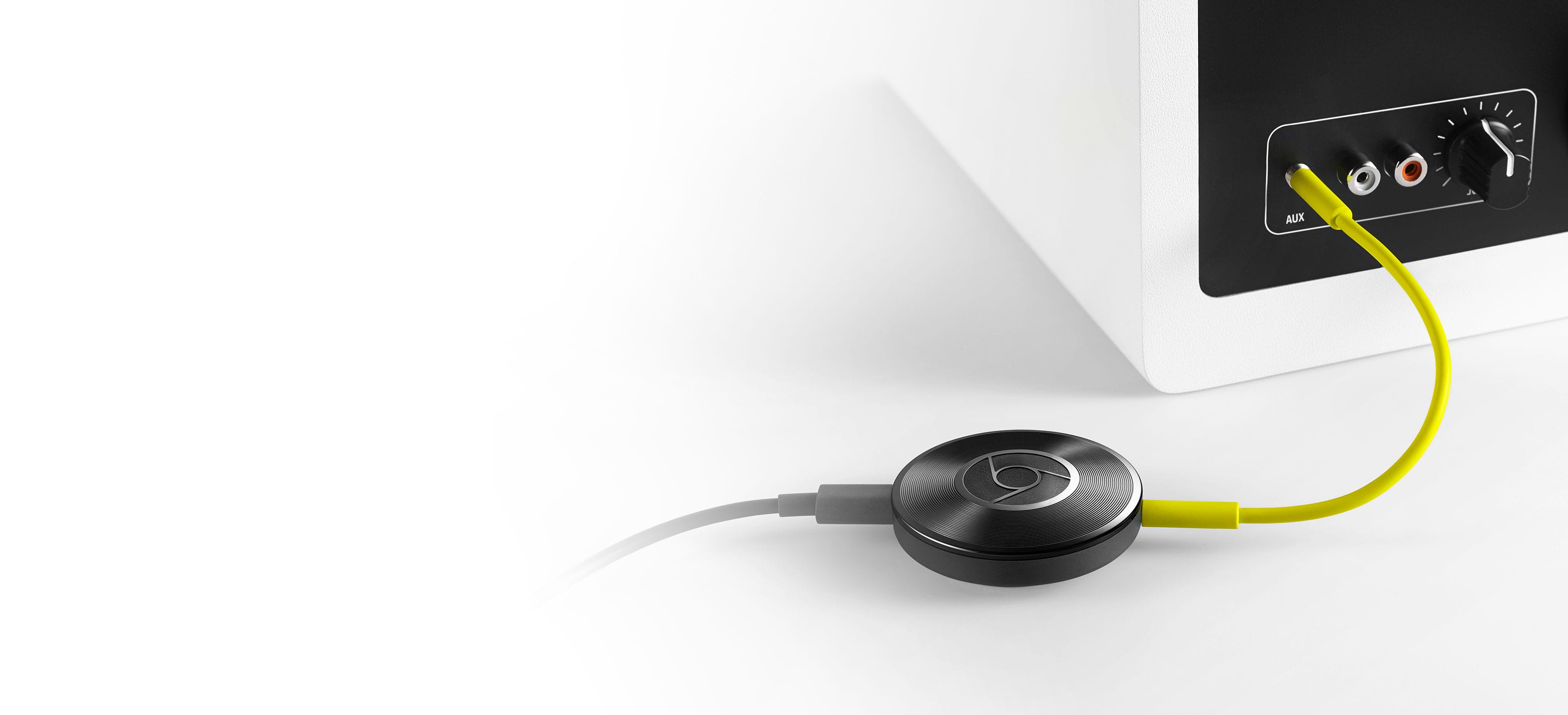
2. Chromecast Audio
With a price-tag of below €40, the Chromecast audio is a cheap and simple device to get Spotify on any speaker or audio system. It is also conveniently small. It gets powered via an micro usb port and with an extra accessory, you can also use an SPIF digital audio cable to connect the cast to your audio system. Setup is simple and straightforward to let it connect to your WiFi router. You can also set it up to allow your friends to connect to it with their android smartphone, so you can have an evening of music sharing.
The Chromcast audio is android phone centered and is not visible for other devices with the Spotify software until you activate it using the Spotify app on your android smartphone. If you use the Chrome browser you can circumvent this by using the Chromecast extension in combination with the Spotify web player. Pro’s: Cheap, small, easy to setup. Con: Really android phone centered.
Chromecast audio
3. DIY project: A Raspberry Pi zero with a DAC.
This last solution is a completely other beast. It’s not the cheapest solution and requires SOLDERING. So let’s list what you need:
A Raspberry Pi zero. This is the most minimalistic, smallest and cheapest of the Raspberry Pies. Because of its popularity, it is also hard to get and the three webshops where you can get them only allow you to order one per customer. There is also this neat little website to see which web shops have them in stock: whereismypizero.com. A single Pi zero costs about €5, but most shops offer them in project kits between €15 and €35.
The Pimoroni pHAT DAC. This is a Pi zero sized digital analog converter board, which uses the same chipset as the much more expensive HiFi-berry full-size boards. A single pHAT DAC board is available for prices between €14 and €20.
GPIO headers. The Pi zero and pHAT DAC only have holes and no GPIO headers, so you have to solder these on yourself. This allows for more freedom to connect the pHAT DAC to Pi zero in different configurations depending on the size of your case. I just soldered a strip of male GPIO pins on the zero and a female header on the pHAT DAC board. You only need 5 pins to make the connection between the Pi zero and pHAT DAC working. I however, used the full 20 pins to make the connection also mechanically stronger.
A Rasberry Pi compatible Wifi dongle, with a micro USB connector or a normal one and a micro to full-size USB adapter. This should set you back for between €5 and €10 euro depending on the shop. Yes, the Pi zero has no onboard Wifi like the Raspberry Pi 3, which is a pity.
A class 10 micro-SD card of 8 Gb or more, to install an OS and audio player software.
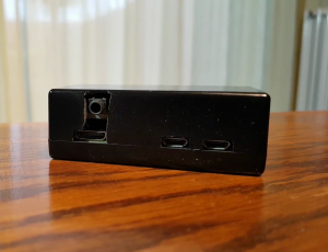
A nice case to put it all in. I opted for this small polycarbonate case I found on amazon. It needs some adaptation to allow access to the 3.5 mm jack of the pHAT DAC and it is a snug fit with the pHAT DAC on top of the Pi-zero, but it is nice full enclosure with access to all ports and the micro SD card slot.
A USB 5V 2 A power adapter to power the Pi zero.
Optional: a USB hub with Ethernet connector, for the initial setup op the audio software on the Pi zero before switching to Wifi. The software used, also allows initial setup using WPS, but I found that to be a bit of plug and pray feature. With a network connection via a cable, your sure it will work.
The Pimoroni Wireless Audio Kit.
In the end, I opted for the Pimoroni pHAT DAC Wireless audio kit which consists of a Raspberry Pi zero, the Pimoroni pHAT DAC, the needed GPIO headers, a WiFi dongle with adapter and A 3.5 mm Jack cable male to male. It also includes some parts I did not use like the micro HDMI to HDMI adapter, the RCA out adapter that can be soldered onto pHAT DAC board and USB to micro USB adapter. But with a price tag at the time of around €30 euro it is still a good deal for the parts I needed. I also bought the USB 5V 2A powersupply for around €6 euro and the USB hub for just below €10. The small polycarbonate case set me back €6. So round and about 52 euro without the SD card, so let’s say €60 with.
The Pi-zero/pHAT DAC in the case. The slit to fit the top of the case over the pHAT DAC board is not very pleasing to the eye but functional.
So on to the assembly of this device, which starts with soldering the GPIO headers on to the Pi-zero and pHAT DAC board. For any instructions on that just look on YouTube, like this video, this or this one. I myself used some blue-tac type putty to stabilize the PCBs on my table to do the soldering. With the GPIO pins and female header attached you can now connect the pHAT DAC board to the Pi-zero. I then modified the top lid of the polycarbonate case with a cutter knife and sanding stick to make a slit for jack line-out socket of the pHAT DAC. It came out to be, let’s say more functional than esthetical. But to my pity, I do not have a Dremel rotary tool to my disposal. It has to be a slit, as the top lid has to slide over the pHAT DAC board with no space to spare and this socket sticks out. With this modification done, the case can be closed. With this, most of the assembly work is already done. You can also find more detailed instruction on how to assemble a Pi zero with pHAT DAC combo elsewhere on the internet, like for example this one.
The next step is to prepare your SD card with an appropriate audio player dedicated OS. As described earlier, there is choice, such as Volumio, Mood audio and Rune audio. For this project my choice was Max2play, which is really multiroom centered and supports Logitech Media Server (LMS) software using Squeezeplayer. I was already acquainted with this system, having a Logitech Squeezebox Duet in use and LMS, with the needed Spotify plugins, running on a local Linux machine. LMS has also the nice feature that you can synchronize playback of your speakers via wifi. Which is ideal for parties when you want the same background music everywhere around the house.
Setup is straightforward: Download the Max2play disc-image (in this case the image with Hifi-berry support) and write it to the SD card. I then inserted the SD card in the assembled Pi-zero, attached the USB hub to the USB peripheral port of the Pi-zero with the Wifi dongle and an ethernet cable inserted, the last of which in turn was connected to my router. I then powered up the Pi-zero using the 5V 2A USB PSU. On another computer I entered the URL: max2play/ and voila the Max2play setup interface was loaded. In this interface I set my Wifi SSID and password, activated Squeezeplayer and indicated that I wanted to use a Hifi-Berry (PI A/B) as audio output to activate the line-out on the pHAT DAC. This initial setup is also explained in this Max2play tutorial video. Then I initiated a shutdown, removed the USB hub and connect the Wifi Dongle directly to the Pi-zero. I could now connect the Pi-zero to the Medion P69055 speaker, select in-line, power up the Pi-zero and voila: A wifi enabled speaker with Spotify that I can control using my smartphone and more importantly with the Logitech Squeezebox duet controller I already used for my HiFi system in the living room. But after a couple of months, my trusted duet controller got battery charging issues, but that’s for another time.
The pro’s: More flexible and fun solution and great sound of a good quality DAC. The con’s: More expensive than the Chromecast, and you have to assemble it yourself. But for me that is half the fun!
Conclusion
So these are some solutions to the issue of no Spotify on the Medion P69055, but of course also applicable to any audio system with a line-in. The “low cost” aspect is rather relative of course, only the old disused laptop with Volumio is really low cost. The Chromecast audio and Pi-zero are 40 and 60 euro respectively and that to fix a speaker which cost me just about €100, bummer! But okay, now it works to my satisfaction so I am fine in the end. You may say that technically non of the solutions are genuinely Spotify-connect solutions. Yes that’s true, but all solutions allow you to play music using your Spotify premium account, they are just not using the Spotify Connect protocol. The Spotify Connect protocol is currently dissected by several enthusiasts, so I expect that this feature will become available for the Raspberry Pi zero in any shape or form. I will be keeping an eye on that. I like the Raspberry Pi zero pHAT DAC combination best as it is the more flexible solution in terms tweakablity. Do you want Apple Airplay or use Google Music instead of Spotify? The Rasberry Pi with Max2play has that flexibility. One thing to keep in mind is to use a good PSU for the Raspberry Pi zero pHAT DAC. Digital/Analog converters are very sensitive to power fluctuation and using a botched PSU may introduce interference. The Medion P65099 has for example a USB charging port, but powering the Pi zero pHAT DAC combination, but also the Chromecast via this port, resulted in background static. Real audiophiles use PSUs with linear power outs, to have the best sound quality, but I this case this is a bit overkill.
There are also other Chromecast audio like devices that are genuine Spotify Connect devices such as the Fon Gramofon and Rocki. Both start at a €65 price tag and especially the Rocki, a former Kickstarter project got bad reviews with difficult setup, bad customer support and melting batteries. The Gramofon I still find quite intriguing as it also uses the same Quallcomm Allplay technology that should allow the Medion P65099 speaker to use Spotify Connect. However with reviews questioning the sound quality of the Gramofon and the price tag of €65 make me hesitant.
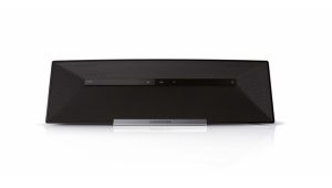
A couple of years back, I bought a wifi-speaker which seemed to have everything for it. It sounds good, it looks good (reddot design award), easy to setup, what’s not to like? I bought this device as a replacement for my radio in my kitchen with idea that I still could listen to webradio but also could stream music using Spotify connect. Yeah, but then your device should be Spotify connect ready, isn’t it? True, there are wifi speakers out there that do not support Spotify connect. But this was not a real impuls buy, and I informed myself well about this device technical background and concluded that it supported Spotify connect. I was however greatly mislead.
The Medion Life P69055 (MD86867)
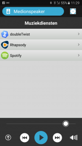
The Medion app even lists Spotify?!
The device I am talking about is the Medion Life P69055 (MD 83867), that I bought just under a €100 at Aldi. Some of you will say, aha Medion and Aldi, whomever would buy an appliance there, its a supermarket! However in my experience and I have owned several Medion Akoya PCs, is that Medion is not great, but far from bad. But still the P69055 seemed to have everything for it. It uses Quallcomm’s Allplay technology which according this press-release by Quallcomm is Spotify connect certified. The Medion P69055 is also featured on the Spotifygear.com website, that lists available Spotify connect devices and as far as I can tell this site is endorsed by Spotify. When I got the device, installed it and started using the Smartphone app to control it, it has a separate menu for streaming services that lists Spotify next to Doubletwist and Raphsody. However when you select Spotify it only starts the Spotify app. In the Spotify app any available Spotify connect device should be seen at the bottom of the screen, but the P69055 never shows up. First I thought this could be due to some port-forwarding issues on my router, but I could put that to bed, after tests with other devices. So finally I called the Medion helpdesk.
Helpdesk BS
I really loath these “non skilled” helpdesks, which only seem to use scripted answers, that only help total nitwits. Sometimes I even seem to hear, that the person on the other side of the phone-line, actually does not understand what they are telling me. Generally, they never know how to deal with a bit more technical savvy person like me. So the advice was to put it in writing on their support page. So I did, added the evidence above to show that it should work and that it was even intended to do so, in view of their own Life-stream speaker control app. The answer I got was total BS, blaming Spotify for not supporting DLNA. A clear diversion of the issue to something outside of Medion’s influence, the oldest tactic in the book. Shame on you Medion!
Where is the firmware?
In the meanwhile I also posted the same question on a Spotify forum and there I got an answer that struck me as more valid. Yes, Quallcomm Allplay devices are Spotify connect certified, but may need a firmware update to work. So I was still positive that a firmware update would arrive and Spotify Connect would start working. The last update was somewhere in the last quarter of 2014, I believe, but no Spotify connect and no more firmware updates since. So I have given up hope that this will ever happen.
Conclusion
I do not know if this is, a can not or will not by Medion, but I can only conclude that the Medion P69055 (MD83867) does not, I repeat NOT support Spotify connect. If Spotify has something to do with the Spotifygear website, they also should remove the P69055 from the list as this is quite misleading. So did you return the device, you might ask? No. it was to late for that. However I thought of a DIY fix, which was an extra cost, but it does the trick. I will eleborate on that in a next post.


 In previous posts I already talked about all these different headless audioplayer operating systems there are for small single board computers such as the Raspberry Pies (eg. Volumio and Max2Play). I also discussed that I am a Spotify user and love the Spotify Connect feature and the multiroom speaker possibility it brings. But the two audioplayer OSes that I am current testing did not support Spotify Connect so far, so I am currently resorting to a multiroom setup using Max2Play, Logitech Media Server (LMS) and the “triode” Spotify plugin to control several devices (RPis with Squeezeplayer software/Squeezebox duet receiver) for audio playback. It works, but the look and feel of LMS is very dated, so I am still on the lookout for improvement and I am not alone. The requested features section of the user forums of both