The woes of Gotek Jumpers for IBM-PC

The Gotek USB floppy emulator, especially with the open firmware Flashfloppy has become a staple for many retro enthusiasts for upgrading old computer systems with a “modern” solution for loading software on the old systems. I am also one of these enthusiasts. As a retro system builder especially of the IBM-PC compatible kind, I am used to configuring these systems using jumpers. No “plug and play” feature here. The Gotek has also some jumpers you must set for using it on an IBM-PC. IBM-PCs make use of a cable that you can connect to two disk drives to one controller.

The selection of which drive is drive A: or drive B: is determined by the distinctive twist in the cable between the connector in the middle and the connector on one of the ends. If the drives you want to connect have jumper for setting the drive ID then both drives need to be set drive ID 0. This is especially the case for most 5 1/4 inch floppy drives, the later 3.5 inch disk drives often do not have drive ID jumpers and are set to ID0 by default.

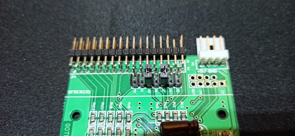
The Gotek floppy emulator has also such a jumper S0 en S1 and this needs to be set to S0. However, there is another jumper JC on the Gotek, which in conjunction with the setting in the FF.cfg file (see highlighted code below the image) for flash-floppy to determine that the drive is in IBM-PC compatibility mode. I configured several Goteks in this way on my retro IBM-PC systems.

The default Gotek jumper setting for IBM-PC, bridging S0 and JC
# Floppy-drive interface mode
# shugart: P2=DSKCHG, P34=RDY
# ibmpc: P2=unused, P34=DSKCHG
# ibmpc-hdout: P2=HD_OUT, P34=DSKCHG (not generally needed: prefer 'ibmpc')
# akai-s950: P2=HD_OUT, P34=RDY (Akai S950)
# amiga: P2=DSKCHG, P34=DRIVE_ID (not generally needed: prefer 'shugart')
# jc: JC closed: ibmpc, JC open: shugart
interface = jc

So having this presumed knowledge I got a new Gotek drive in and set the S0 en JC jumper and connected. But to my surprise, the drive did not work. Troubleshooting went from, checking the FF.cfg on the USB drive used, trying different locations on the cable, using a known working cable, checking with a known working Gotek and floppy drives, also in combination with the new Gotek at different positions on the cable, even reflashing the firmware and checking the disk controller. All to no avail. I even started thinking I was duped out of my money by a fake unit. So I started examining the board of the Gotek. I knew there were different incarnations of the thing, some versions best to be avoided. Then I noticed that the New Gotek was different from the previous working one.

Two different version of the Gotek, left my older SFRC9220 and to the right my newer SFRKC30.AT2 version. Note that label JC is missing from the third jumper from the right.

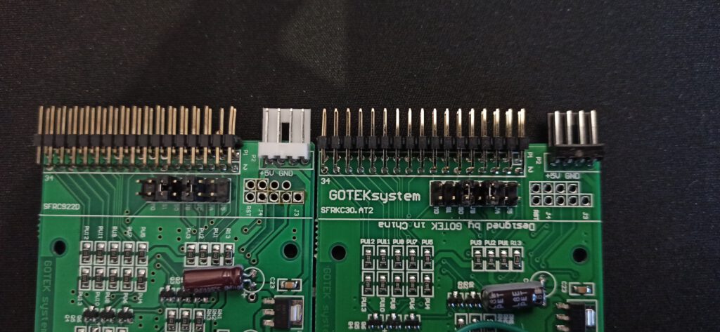
Gotek SFRKC30.AT2 has no JC jumper!!

The older Gotek I had laying around had as board number SFRC9220, the newer Gotek was labelled “GOTEKsystem” with board number SFRKC30.AT2. I was already reading through the Flashfloppy wiki to see what could cause the problem and was now looking for information on this particular iteration of the Gotek. In the Gotek compatibility section, some are listed and there I noticed this side note: “SFRKC30.AT2 (QFN32): Missing the original rotary-encoder header, but features the new KC30 rotary header. Also missing JC jumper location.”. A bit confused I looked back at the board and now noticed the JC label was missing from one of the 7 jumpers, but there was a jumper header. This jumper header is not functional, so even when bridged a Gotek SFRKC30.AT2 with USB stick having the interface=jc setting activated in the FF.cfg file, will think the drive is in shurgart mode not ibmpc mode. And voila, changing this setting in the FF.cfg file from settings=jc to settings=ibmpc made my new Gotek work flawlessly on my 286 build.

So to summarize, when using a Gotek with board SFRKC30.AT2 in an IBM PC compatible, you only have to set jumper S0 and make sure that the flashfloppy FF.cfg file has the interface parameter set to ibmpc and not jc.

Controlling your C64 not with a mouse, but with a R.A.T

A part of my retro-computer collection consists of several Commodore-64s. The C64 was the computer that I wanted as a 12-year-old but did not get… I am only discovering it now. One of the machines I have was a great secondhand deal.

It’s a C64 complete with a datasette player, floppy drive everything had still its original box. I also came with an extra box, with random computer stuff. Besides a collection of cassette tapes with software and a collection of EPROMs, the previous own programmed custom kernals, this box also held a strange peripheral that I had not seen before. A beige box with a black cable having an 9 pin joystick connect attached and one clear led, or at closer inspection an IR receiver. The box had only a label on the top reading “Cheetah”. On the bottom were 3 rubber feet, but no label with a model number of sorts. At first instance, I even doubted if this was a genuine sold product or someone’s DIY project.

The beige box in Question

Because I thought it was a wireless, IR-controlled peripheral, I started Googling with catchwords such as “infrared” “joystick” “c64” “cheetah” with images, but I didn’t see the box that I had before me. But via the name Cheetah, actually Cheetah Marketing, a British manufacturer of peripheral devices, mostly joysticks for the 8-bit computer generation and also sound and music-related peripherals, I came across the Remote Action Transmitter (R.A.T.). The different articles only referred to the version for the ZX spectrum and mostly to dated photos of what that thing had looked like. But in the end, I also found an episode (#34) of Paul Jenkison’s “Spectrum Show” on Youtube where this device is revealed. It consists of an IR receiver in the form of a plug-in module for the ZX spectrum (which did not have a joystick port) and instead of a joystick, a remote control with a joypad and fire button designed as membrane buttons. So I went digging in the box to see if I could find a remote control and yes it was.

The controller as shown in episode 34 of Paul Jenkinson’s Youtube channel “The Spectrum Show”

This remote control is identical to the one shown in the “Spectrum Show” episode. The remote control gets its energy from a 9V block battery and has two IR transmitters on the front. For operation, you need two hands because you operate the fire button with one thumb and use the other thumb for the joypad. The joypad is of course not analogous like a “real” joystick. There are eight specific positions that the joypad recognizes and transmits to the receiver. In my case, it is the receiver that makes it special, because it can probably be used on all machines with an 8 pin joystick port (Commodore, Atari), instead of the specific ZX spectrum plug-in module. Anyway, would I really like to use this thing? The idea of having a wireless game controller in 1984, it is way ahead of its time. Wireless controllers have only become commonplace with the fifth generation of consoles in 2005-2006. The implementation of the idea in 1984 is not good and actually more of a gimmick. The fact that you have to use the thing with both hands and aim properly and still are “treated” with poor response times, makes it more aggravating than something useful. The device can indeed be used from quite a distance but it also means squinting to see the little CRT of that era. No, in my view the R.A.T. more a nuisance, then a blessing. Probably, therefore there are very few left, and that makes it a rare item.

A drawing of the initial design of the R.A.T., rather as a joystick, in Cheetah patent application GB2158667

On one of the advertisements for the R.A.T., I saw “Patent Pending”. This aroused my interest because I know my way around the various patent databases. Could I trace the patent on that device? Yes, the British patent no.2158667 filed by Cheetah Markting on May 3, 1984 and granted on January 20, 1988, describes the wireless game controller. However, the configuration in the drawings differs from the device that appeared on the market. The controller started more as a joystick than a joypad. A joystick with two fire buttons on the handle which would make moving and firing with one hand possible. However, I see that this design would have led to problems. As said earlier, the infrared transmitter can only encode eight specific positions and send them to the receiver. To overcome this for a joystick, which can in principle take up an infinite number of sub-positions, the thought of something. The patent shows a joystick, that cannot move around freely, but an opening in the form of an eight-pointed star in the foot guides the user of the joystick to one of the 8 positions when moving the stick from the centre, from one position to the other is therefore only possible by returning to go through the centre. This looks like an innocent idea, but every joystick user knows what the scenario will be if you start to play. In the “heat of the moment” you will use force and break the stick or the foot. I wonder if Cheetahs engineers realized this, redesigned it as a joypad or that real joystick prototypes were made that broke after a short torture during testing. One can only wonder.

Retro tech: The Philips EL3515A

So far my blog and video’s has been about DIY tech stuff with a focus on audio. This time we stay in the realm of audio but go back time. Way back even before even I was born, because I would like to show you an old audio device that I saved from the skip somewhere in the 1990’s but was produced in the late fifties early sixties. It even still works (sort of). It’s an old table-top reel to reel tape recorder made by the technology pride of the Netherlands: Philips, more specifically the EL3515A model. This EL series of reel to reel tape recorders have been produced by Philips from 1957 onwards to 1968. But this EL3515A is an early model. The “A” indicates that it is a more luxurious version of the basic EL3515, with a wooden case covered with fake leather instead of a plastic case. It is pre-transistor device and its electronics is still based on radio tubes. One of the tubes is used for the “magic eye” which is in the big stop button, which lights up green when the device is on and should show the recording level. This is one of the first models with such a “magic eye”. The whole package comes in the form of a carrying case that is 370 mm wide,  160mm high and 320 mm deep.

The power cable and a separate mono microphone can be tucked away in a small compartment on the right side of the case with a removable lid. The whole thing has a hefty weight of around 8 kg, mainly because all the electronics and moving part are mounted in a cast-iron frame that resides in the wooden case. Because of this, I would not call it a mobile device. It runs off AC power switchable between 110, 127, 220 and 245 Volts. It is a mono device with around 2-2.5 Watts output. When you remove the plastic cover, you can see that it uses 9 to 13 inch tape reels. It plays and records two mono tracks (two sides) running at a speed of 9.5 cm/s.

After plugging in the power socket, you can switch it on by turning the left volume button. The whole thing directly springs to life with the hum of the drive motors, but playback can only be heard after a short warm-up until the “magic eye” is at its full intensity.  It is very basic machine, the extreme left and right buttons are for winding back and forth, then you have on the left, a pause button, on the right the play button and the big button in the middle with the “magic eye” is the stop button.  Between the two reels there is also a counter present, but this is broken on this machine. The turning nobs on the extreme left and right are on/off and volume left and the recording level on the right. The smaller nobs next to them are tone adjustment on the left and the red recording button on the right.

The “magic eye” lighting up in the stop button

When I rescued it from the skip somewhere in the 1990’s, it still worked fine and I used it as a novelty when my little nieces and nephews were visiting to record their voices and playing them back to them. That was always a lot of fun. Now it seems that the amplifier part of the device has deteriorated, playback and recording levels are low. It first off all would need a thoughrough cleaning. As it is now standing in storage, I am thinking to sell it off. Its seems that there are still some enthusiast out there who collect these things or scavenge them for the radio tubes. These tubes seem then to find their way into all kinds of DIY projects. When researching this device for this blog and my youtube video. I also came across an advertisement from the Leidsche courant from 1959 with prices for the EL3515, EL3515A and the more advanced EL3538. The EL3515A was priced at 398 Dutch guilders in 1959, which translates in a value of € 1 219.42 in todays money (Calculated with the tool here.), but I think I will make my asking price as a serious lot lower! If you want to see the EL3515A in action please watch my youtube video below.

The EL3515A in an Dutch advertisment from 1959